Take the panels off.
Explore a commercial rooftop unit.
Follow the air, refrigerant and economizer.
The interactive controls need JavaScript. You can also read the operating model and source notes below.
The mixing box
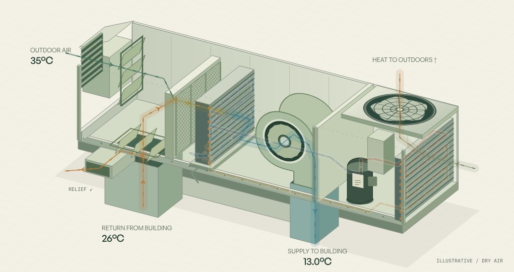
Outdoor and return air meet here. The linked dampers change their proportions before the air reaches the filters.
Warmer air in. More heat to move.
Outdoor air is needed for ventilation. When it’s warmer than the return air, opening the damper further adds to the sensible cooling required.
Put someone else at the same controls.
Copy a link to your temperatures, economizer and circuit view.Keep the whole service day connected.
BoltWright is software and AI for commercial HVAC service teams. Plan the visit, find the equipment history, and turn the crew’s notes and photos into reports your office can review.
A little theory.
A lot happening.
A generic, single-circuit, cooling-only packaged rooftop. The cabinet is cut away and pipework is simplified to make the paths visible.
Give the air somewhere to go. Try the Ductulator ↗What this model does (and doesn’t)
A steady-state, dry-air heat balance with a continuous call for cooling. We choose a 13°C supply target, 1 kg/s supply-air mass flow and 20% minimum outdoor-air share for this illustration. These are teaching assumptions, not ventilation requirements or service thresholds.
Mixed temperature = outside share × outdoor temperature + recirculated return share × return temperature. The fixed return flow splits before the return damper: relief mass flow equals outdoor-air intake, and the remainder recirculates. Sensible cooling required = 1.006 kJ/(kg·K) × 1 kg/s × max(0, mixed temperature − 13°C). The coil is assumed to have enough capacity. If mixed air is already below 13°C, it passes through without mechanical cooling or reheating.
In Auto, a simple differential dry-bulb controller admits more outdoor air when it is cooler than return, up to the amount needed for the supply target. In manual mode, you set the share directly, including positions outside the example automatic sequence.
There is no humidity or latent load, fan heat, pressure drop, leakage, capacity limit, compressor staging, refrigerant property model or time delay. The displayed kW is a heat-removal requirement, not equipment capacity, electrical consumption or a savings forecast. Colors identify paths, not measured refrigerant temperatures. Air-path widths show relative mass flow. Particles and permanent arrows show direction, not velocity. Coil colors progress in flow order. Their transition locations are illustrative; they do not reproduce actual coil circuiting or refrigerant properties.
Air and refrigerant are separate circuits
Building air passes over the evaporator. Refrigerant stays inside its tubing. The compressor circulates refrigerant through the outdoor condenser, expansion device and evaporator. The condenser uses its own outdoor airstream; it does not send that air into the building.
Compressor and condenser-fan motion stop here when sensible cooling is zero. Real units have their own fan, staging, protection and humidity-control sequences. The inactive circuit is a component map, not a prediction of off-cycle pressure or refrigerant phase.
Technical sources
Trane: Keeping Cool with Outdoor Air, Airside Economizers (2006). Operating principles, mixing, relief air and integrated mechanical cooling. Its historical code discussion is not used as current guidance.
Trane: Compressor and Refrigeration Cycle. Compressor function, heat transfer and refrigerant states.
Trane: Delivering Performance from Airside Economizers (2016). Air mixing and the practical limits of ideal mixing.
Trane: Direct-Drive Plenum Fans and Fan Arrays (2010). Housed centrifugal fans, scrolls and outlet direction. Sources reviewed September 11, 2026.
This illustration is not a manufacturer-specific simulation, diagnostic instrument or repair procedure. Equipment layout and operating sequences vary.